Miata Headlight Prototyping
Headlight Prototyping… Again
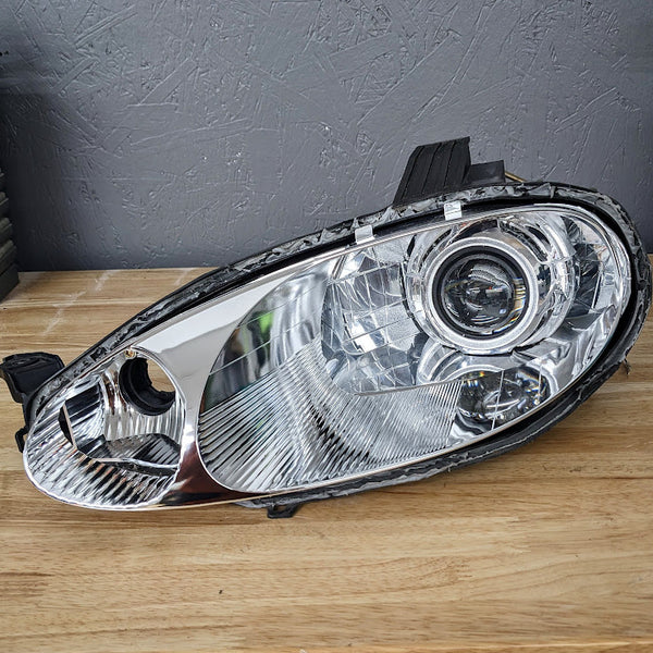
Alright, so I’m looking to redo my foggy headlights. The last time I worked on them, they didn’t seal properly and ruined the headlight lens. I am considering ordering brand new headlights and swapping the DRLs and MLED into the new housing. The best pricing I’ve found so far is:
- Driver Side - $256.11
- Passenger Side - $256.11
For looks, I was talking to Matt over at Left Lane Designs, and he gave me this image. I wasn’t a huge fan of it at first, but when I considered this setup with custom DRLs, ooh damn, will it look good.
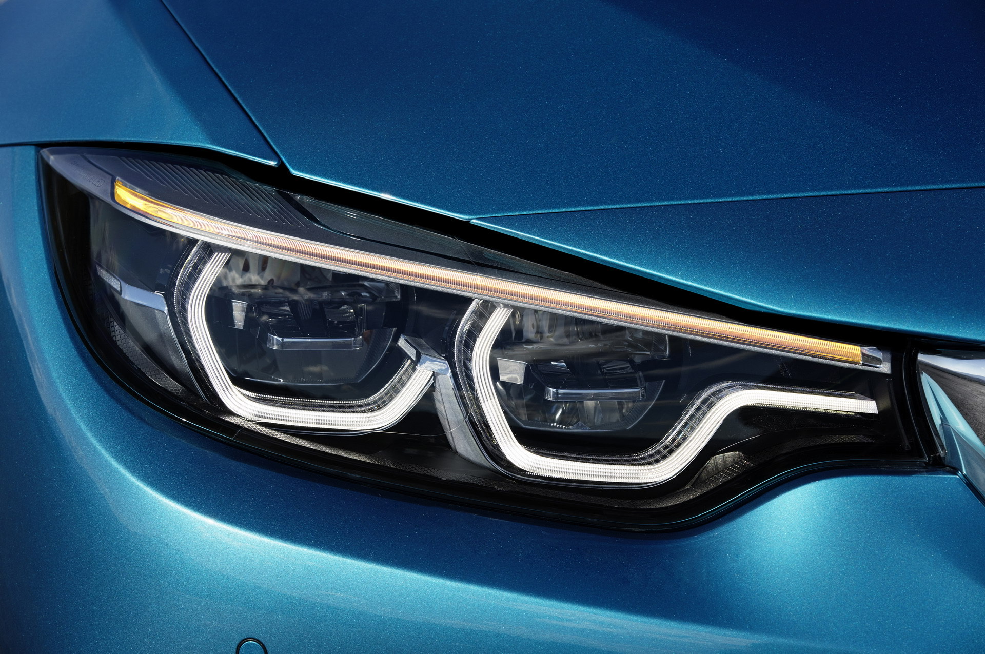
So what is this custom DRL you ask? Well, it’s basically making my own version of the BMW angel eyes.
But how do we make these? Well, 3D printing of course, and some custom electronics.
Alright, after some planning and other shenanigans happening, I have decided to use:
LED Parts List
- XIAO ESP32C3 as my microcontroller because it has built-in Bluetooth and is small and compact. My main worry for the ESP32C3 is heat, but this will be monitored in testing.
- A total of 7 TLC59401RHBR as the LED drivers.
I need to connect a 41.2Ω resistor to one of the IREF pins of the LED driver, but I will double check this. At the time of writing this section, it is planned to use 101 LEDs: 55 per color of Yellow and Cool White. I do not have accurate measurements at this time.
- LEDs will be the KingBright APTB1612SYKQWDF, some really fancy Bi-LED SMD LEDs with low power usage as well.
Power Draw Calculations
Each LED channel current: 20mA (set by the IREF resistor).
Total LEDs: 108.
Total current for LEDs: 108 × 0.02A = 2.16A
TLC59401RHBR drivers:
Operating current (for logic and internal operations): typically a few milliamps per driver. We’ll estimate 10mA per driver for seven drivers: 7 × 0.01A = 0.07A
XIAO ESP32C3:
Operating current: typically around 50mA when active.
Total Current Draw = 2.16A + 0.07A + 0.05A = 2.28A
Total Current = 2.28A
So, knowing the whole system will draw around 2.28A, I will need to find a ~12V to 5V 3A buck converter.
Keep in mind when a car is running, voltage will fluctuate because of the alternator to as high as 15V.
Coding Stuff
Current setup on a test bench setup with an Ardiuno Uno and 11 Single color LEDS. I orginally used delays for the lights but after a post on youtube someone suggested I use Millis for faster animations, used it in a simulator on tinkercard found here
1
2
3
4
5
6
7
8
9
10
11
12
13
14
15
16
17
18
19
20
21
22
23
24
25
26
27
28
29
30
31
32
33
34
35
36
37
38
39
40
41
42
43
44
45
46
47
48
const int startLEDPin = 3; // Start of LED pins
const int endLEDPin = 13; // End of LED pins
const unsigned long interval = 100; // Interval between LEDs in milliseconds

int currentLEDPin = startLEDPin;
int direction = 1; // 1 for moving right, -1 for moving left
bool animationComplete = false;
unsigned long previousMillis = 0;

void setup() {
  // Initialize all the LED pins as outputs
  for (int pin = startLEDPin; pin <= endLEDPin; pin++) {
    pinMode(pin, OUTPUT);
    digitalWrite(pin, LOW); // Ensure all LEDs are off initially
  }
}

void loop() {
  if (!animationComplete) {
    unsigned long currentMillis = millis();

    // Check if it's time to move to the next LED
    if (currentMillis - previousMillis >= interval) {
      // Move to the next LED
      digitalWrite(currentLEDPin, LOW); // Turn off the current LED
      currentLEDPin += direction;

      // Check for direction change
      if (currentLEDPin > endLEDPin) {
        direction = -1; // Change direction to left
        currentLEDPin = endLEDPin - 1;
      } else if (currentLEDPin < startLEDPin) {
        direction = 1; // Change direction to right
        currentLEDPin = startLEDPin + 1;
        animationComplete = true; // Animation is complete
      }

      digitalWrite(currentLEDPin, HIGH); // Turn on the next LED
      previousMillis = currentMillis; // Save the time of the last update
    }
  } else {
    // Turn on all LEDs after animation is complete
    for (int pin = startLEDPin; pin <= endLEDPin; pin++) {
      digitalWrite(pin, HIGH);
    }
  }
}
Starting the Work
I was fianlly able to convince dad to let me bake open at least one headlight light, so that’s exactly what I’ve done and here is a quick rundown of how I did it uninstalled headlight on miata > preheat oven to 185°F > Place headlight inside oven on a layer of parchment paper > bake for 10 min > Pull headlight out of oven > use a flat head to seperate headlight than pull apart.
However if I was going to be reusing this headlight do not use a flathead as you could ruin the seal, morimotot makes a special tool to open headlights. just use that I couldn’t find mine this day and since I wasn’t going to reuse the headlight I didn’t care. but Now only grabbing messurements for the DRLs.
Oh and I had also orderd the apollo 2.0 Full and Flat projector shrounds as they will become the new shrounds with these DRLs. will provide photos once I format them correctly
Trimming Shrouds
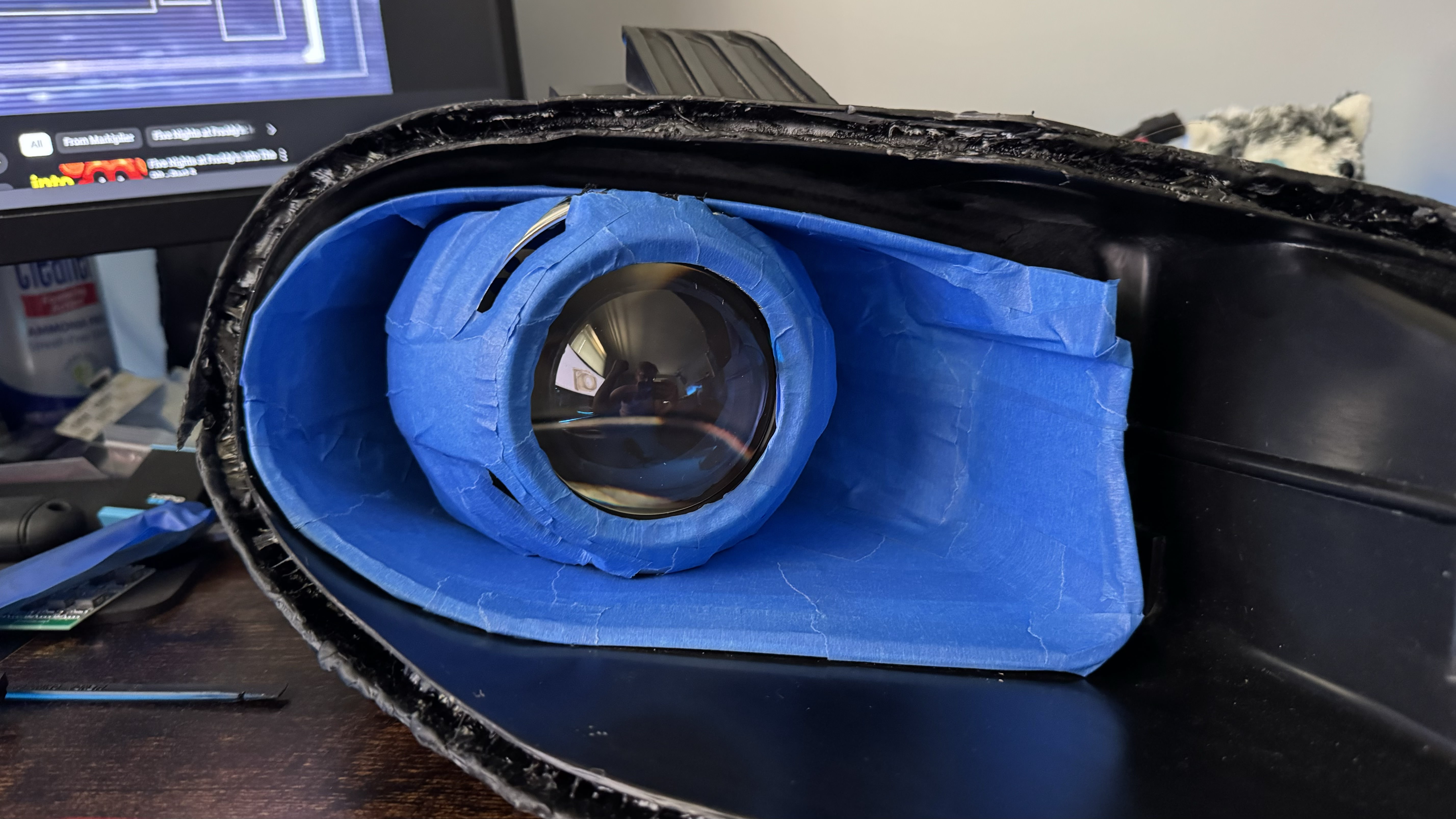
I began by trimming the headlight shroud but couldn’t find my Dremel, so I had to use some flush cutters I had on hand.
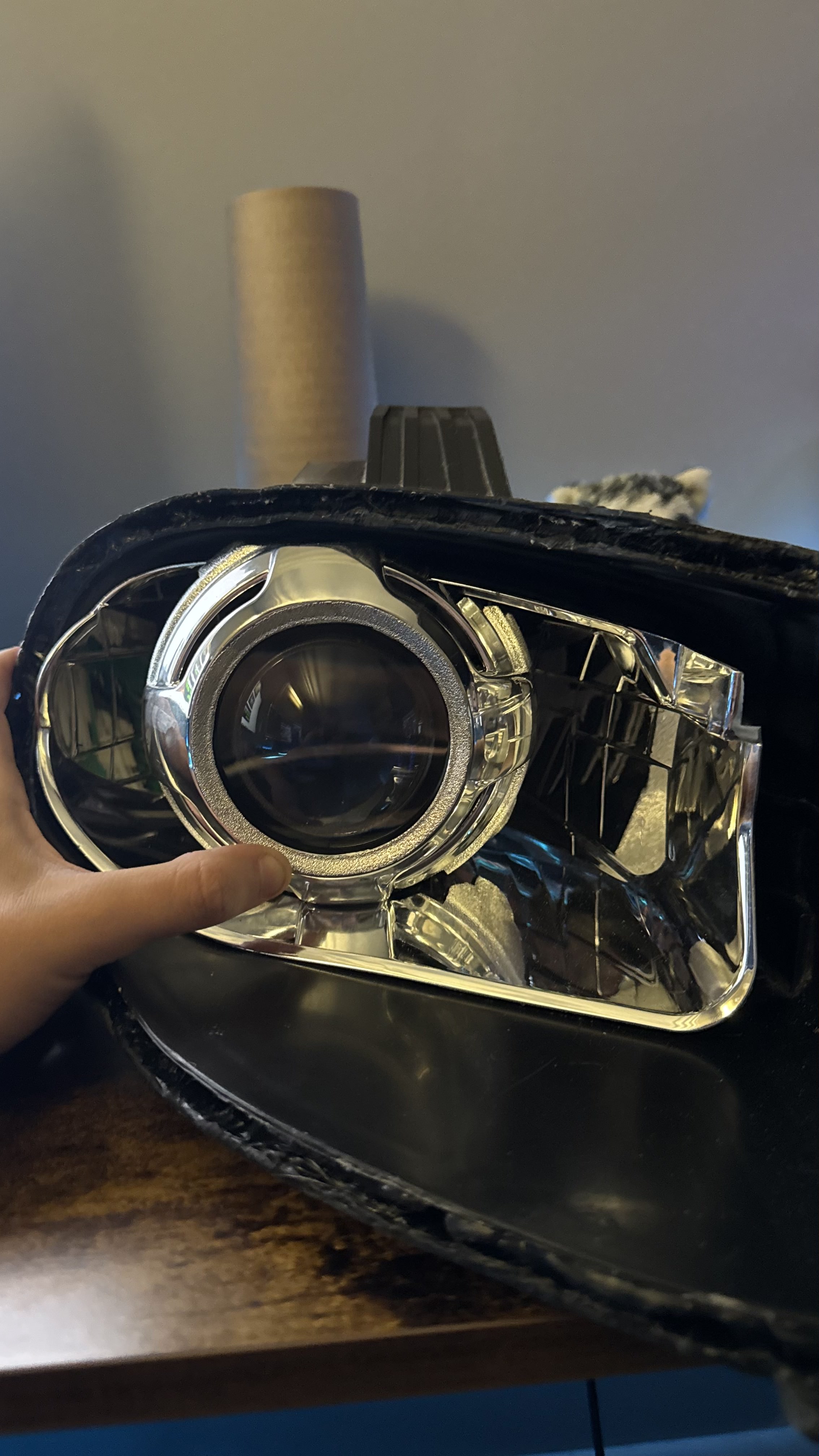
The image shows my first few hours of cutting, where I managed to remove most of the bottom half and a small portion of the top. However, as I continued, the process became tedious, with me making increasingly smaller cuts. Realizing I was spending too much time on this, I decided to invest in a new Dremel. It was absolutely worth the money, as it made quick, clean work of the headlight shroud, unlike the flush cutters.
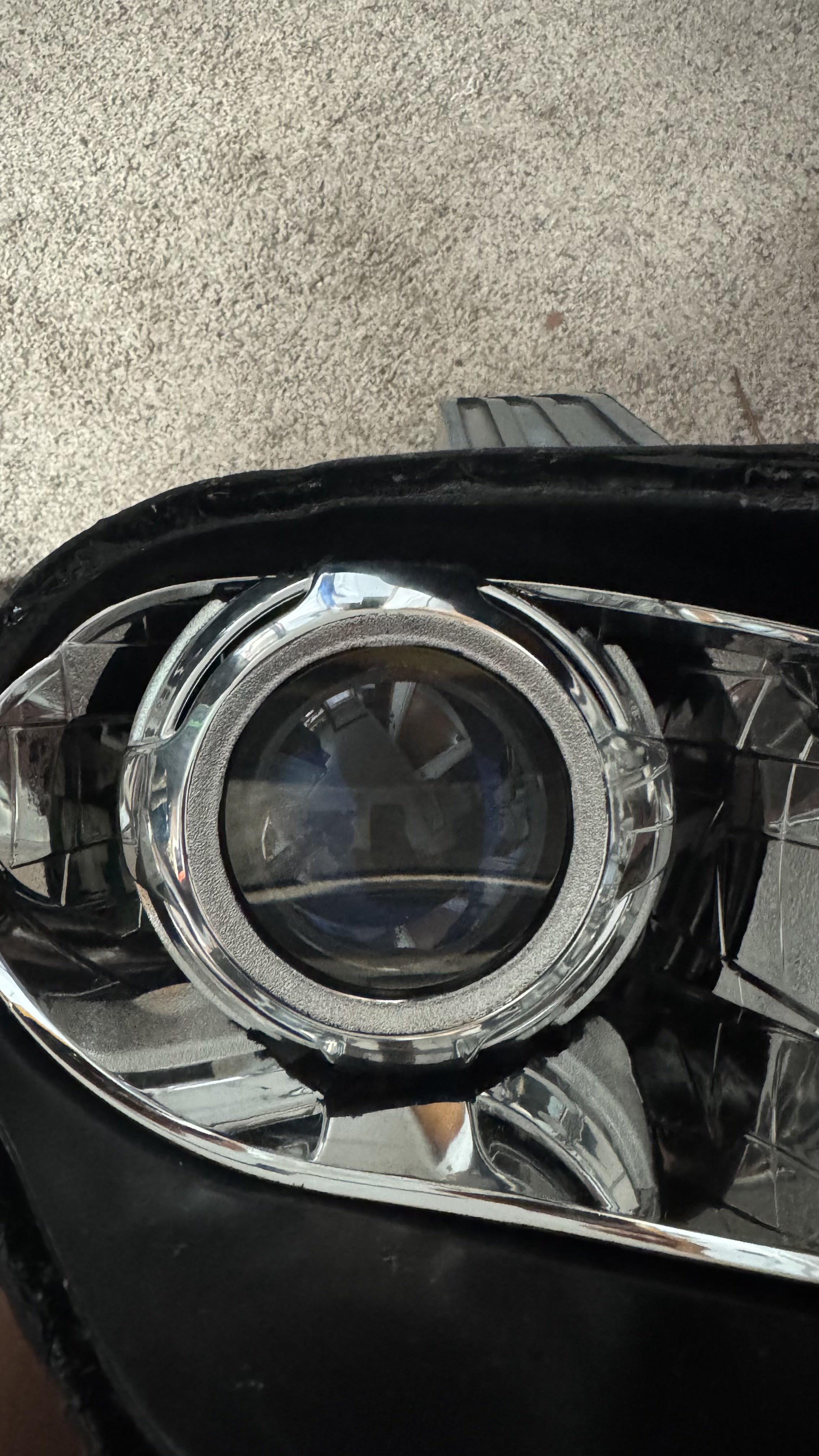
This image shows the headlight in an almost finished state. Once I was satisfied with the trimming, I began working on the custom DRL (Daytime Running Light) dimensions.
DRL Designs
Using Fusion 360, I created a rough draft for the DRL headlight design and took measurements with a digital caliper.
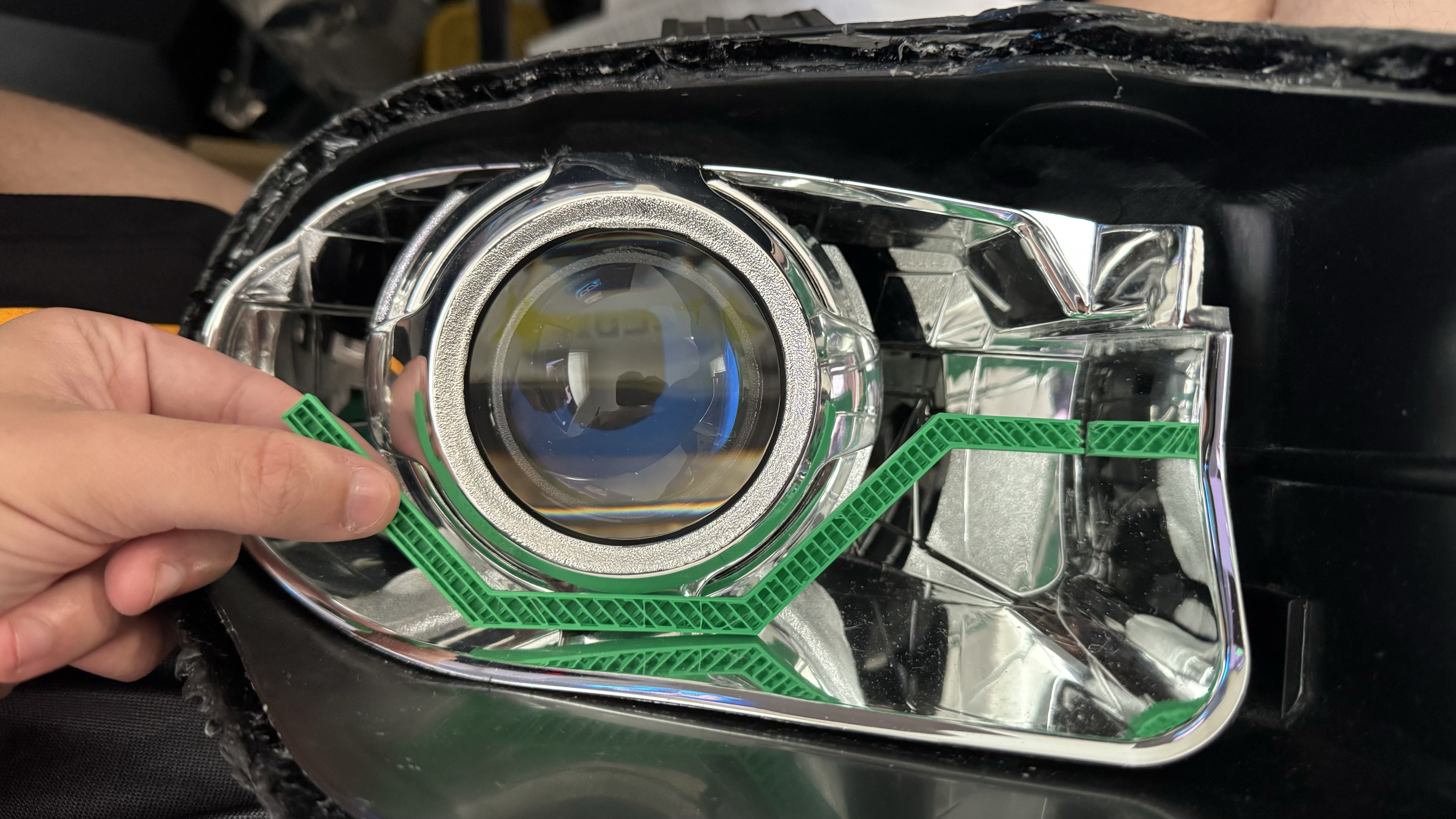
As you can see, my first print fit decently, but I felt it was too sharp and steep for the style I wanted, similar to the M4 headlights. I decided to go back and redesign with improved measurements, leading me to this version.
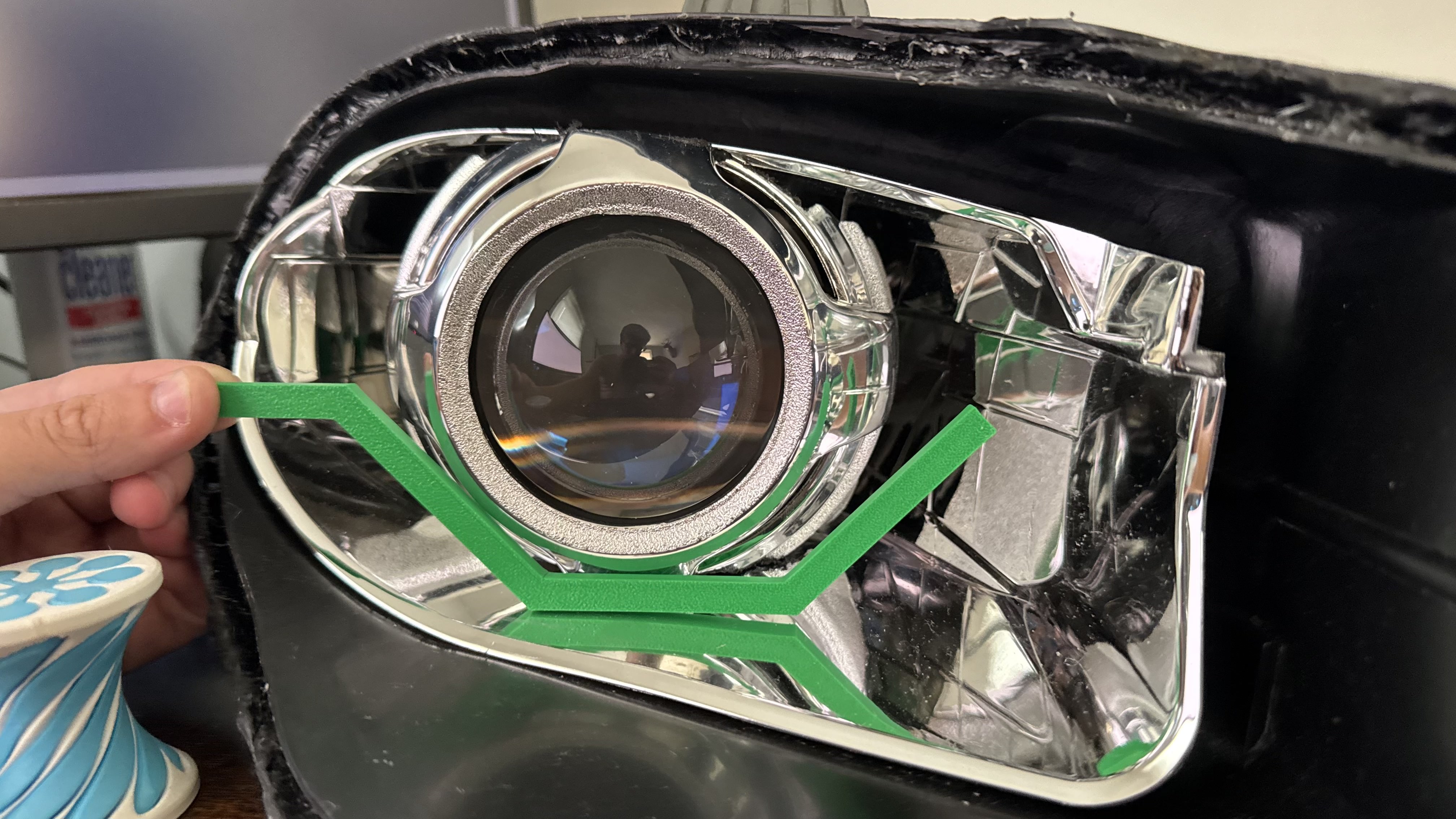
In this photo, I’m holding the DRL in the wrong direction, which eventually led to several different designs. Finally, I settled on the following.
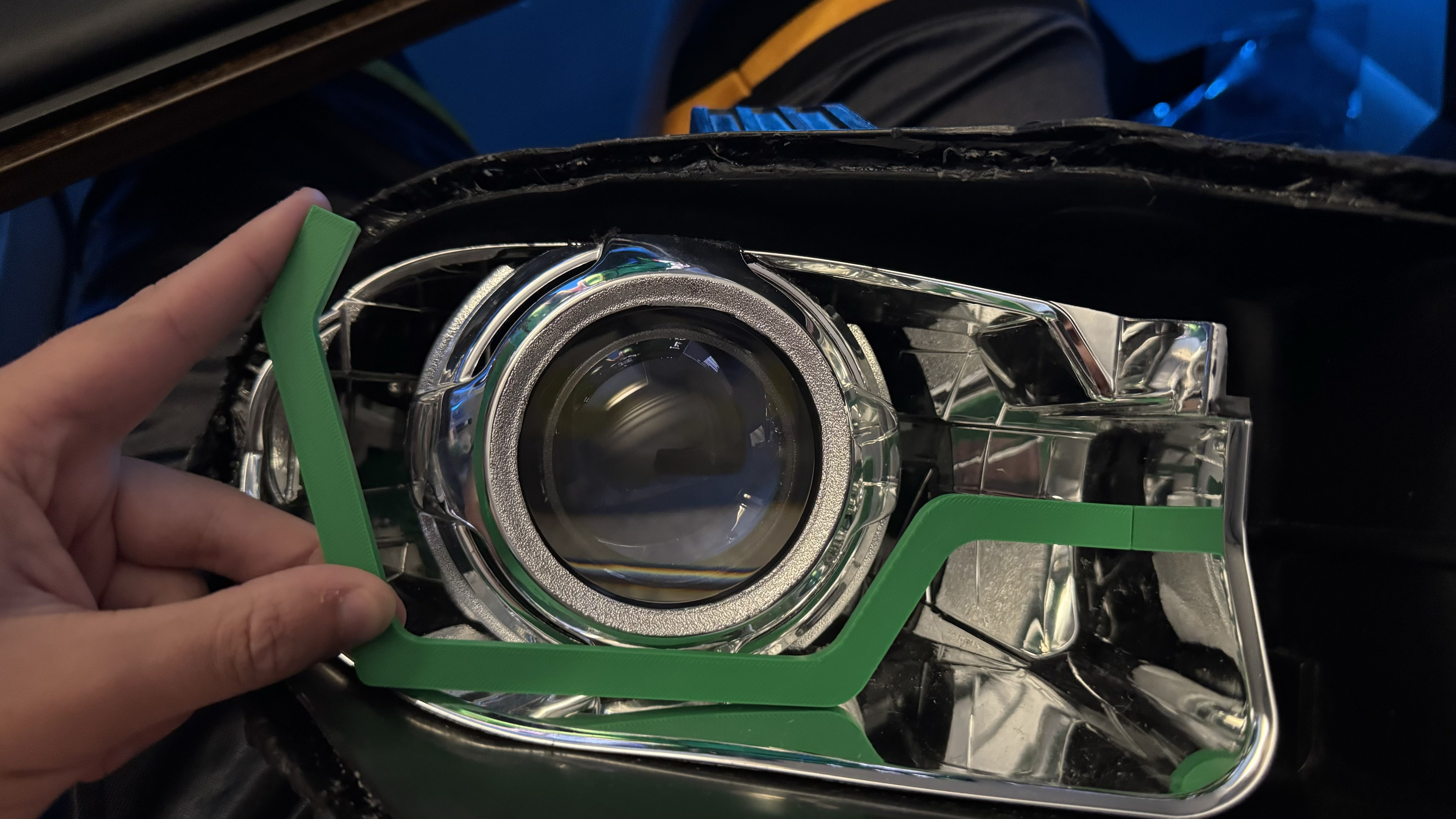
This is by far my favorite design, but I need to make the shape follow the curve of the headlight. The only way I could figure out how to do this was to create a 3D scan of the headlight. However, reflective surfaces don’t work well with 3D scanning, so I decided to do the only thing I could think of.
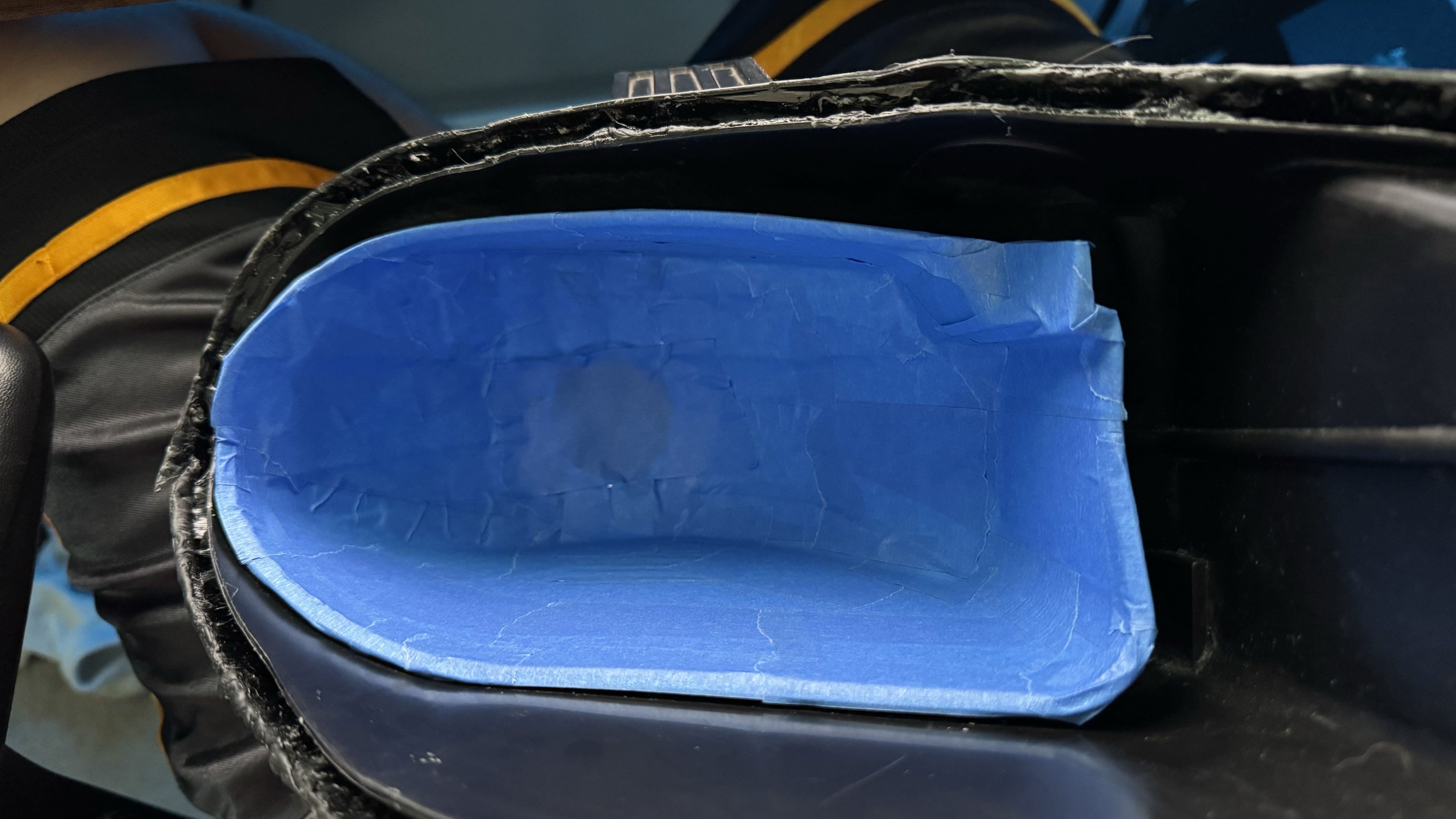
As of writing this last section. Im currently working on taking the scan I got from this headlight and adapting my shaping to it